
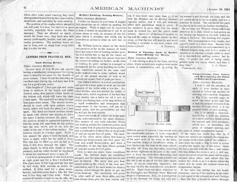
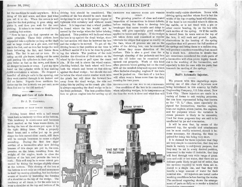
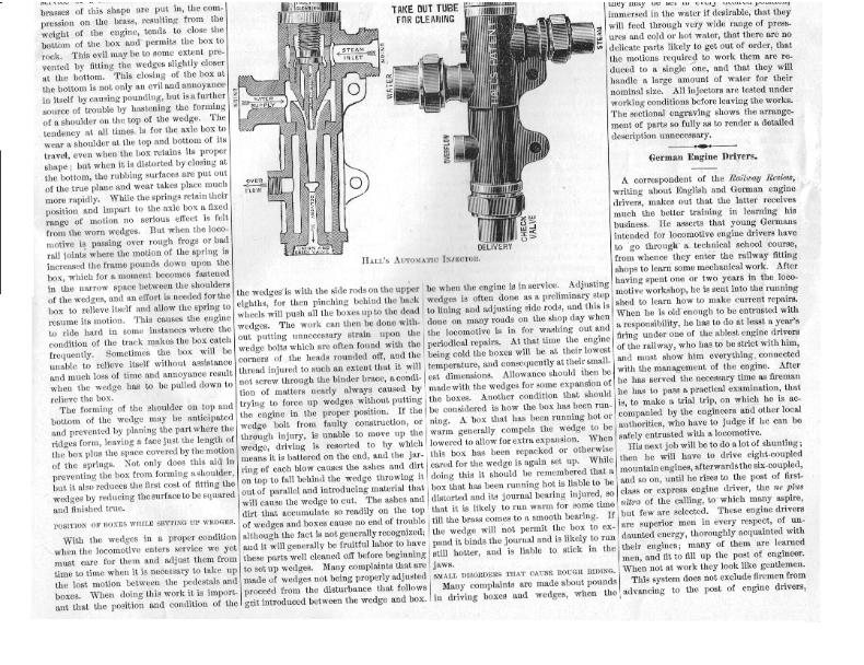
AUGUST 30, 1884] AMERICAN MACHINIST 5 let the machines be made anywhere. It is a thing of life and sense, and does just what you tell it to do. When the cotton is well open for the first picking it goes along and picks it, and then you wait for the next picking. It takes in no trash or dead leaves —nothing but cotton. "Now he has a gin that operates on the same principle. These little pickers have expanded into a cylinder as long as the shaft and as large round as a gin saw, and they catch the lint, and an iron bar keeps the seed from following the lint, and forces them back. The lint is not cut or torn. He is using an old gin frame, taking out the saws and putting his cylinders in their place. It gins twice as fast as the saws, and there is no danger to hands or arms. I put my open hand on the cylinder while it was making j2,000 revolutions a minute. He dropped a handful of shingle nails in the opening, and they were carried through in an instant and did no harm. Experts from northern factories say the lint is worth ten per cent. more than lint cut by the old method." Fitting and Care of Axle Boxes. By J. 1). CAMPBIEI;r,. INFLUENCE OF hIAlF ROUND BRASSES. Driving boxes fitted with a half round brass have a tendency to close at the bottom. This tendency is continuous and becomes most marked as the brass wears down, relieving the box of the strain put upon it by the tight fitting brass. With it properly fitted brass and a collar 'put up in good shape the box cannot close much, still there will be enough looseness to cause a slight pounding. During the first few days' service of a locomotive after new driving brasses of this shape are put in, the compression on the brass, resulting from the weight of the engine, tends to close the bottom of the box and permits the box to rock. This evil may be to some extent prevented by fitting the wedges slightly closer at the bottom. This closing of the box at the bottom is not only an evil and annoyance in itself by causing pounding, but is a further ~~..r of trnnhlh by hasteninLy the formingdriving box should be considered. The position of the box should be such that the wedge may be set up to the proper degree of tightness with certainty and without much labor. It is important that a wheel position be found where the box would. not be moved by the wedge when the latter is being adjusted. This position will be found where the box is up against the dead wedge, since the lost motion will then be between the box and the wedge to be moved. To get all the driving boxes in that position at one time is a difficult matter if it is to be done by pinching the wheels. The position of the rods decides the direction of their action on the wheel by the thrust or pull upon the crank pin. If the-rod is above the wheel center, pinching behind, the back wheel will force both the wheels and boxes on that side up against the dead wedge; but should the rod be below the wheel center similar work with the pinch bar will draw the forward box away from the dead wedge, the side rod doing this by pulling on the crank hin----this is always supposing the dead wedge to be in the front pedestals. The best position therefore to get an engine into for setting up all NECESSITY FOR KEEPING BOXES AND WEDGES CLEAN. The growing practice of close and stated inspection of locomotives to detect defects, before waiting for them to develop into breakages that cause trouble and delay to trains, will give especially good results if applied to boxes and wedges. If the wedges are taken down and examined at regular intervals the ridges that appear so readily on the face, when oil grooves are cut on the sides of the driving box, can be smoothed off before they cause distortion of the surface. This is also a good time for a thorough cleaning of the pedestals and box and the oil holes can be examined and opened out properly. Work of this kind often prevents boxes getting hot on the road' with all the entailed delay and expense which' often includes changing engines if the train must be pushed on. One turn of a hot box will often wear a brass more than the daily running for two years. TEMPERATURE OF TJIE BOX TO BE CONSIDERED. One condition of the box to be considered when adjusting wedges, is its temperature at the time the work is done and what that willtrouble really exists elsewhere. Boxes with driving spring saddles whose foot is but the width of the top or spring band will ofttimes, if the band is not rounded where it rides on the saddle, or is not fitted with a pin or other center bearing, tip on the box with each motion of the spring. Or if the saddle is moved from its worn seat on the top of the box, it will rock and pound. Again, obstructions in the bearing of the spring equalizer that will prevent the full motion of the springs and bring them to a sudden stop, will produce a motion resembling that caused by a stuck box. Attention to details that are sometimes considered the crude parts of a locomotive will often prove highly beneficial to the working of the locomotive, and especially is this the case with the parts that transmit the motion of the springs. Hall's Automatic Injector. We present with this engravings representing one of this class of injectors now being introduced in this country by Hall's Engineering Company, 112 John street, New York City. These injectors are made in a variety of forms to suit varying purposes, the one here represented being that known as the " D. L." class, more especially designed for locomotives, traction engines, tram-car engines, steam yachts, fire engines, and for purposes where the variation in steam pressure is likely to be excessive. Used for these puposes they are said to be unaffected by jar and concussion. It will be seen that, by means of the screwed top, the spindle and attachments can be most readily removed, should it become necessary, for cleaning, the time required for doing this being very short. It is claimed for these injectors that they are very simple in construction, that they are made in variety to suit (every purpose, that they may be set in every desired position, immersed in the water if desirable, that they will feed through very wide range of press- ures and cold or hot water, that there are no delicate parts likely to get out of order, that the motions required to .work them are reduced to a single one, and that they will handle a large amount of water for their nominal size. All injectors are tested under worldiw conditions before, hln.vinn thn wnrka_ brasses of this shape are put in, the compression on the brass, resulting from the weight of the engine, tends to close the bottom of the box and permits the box to rock. This evil may be to some extent prevented by fitting the wedges slightly closer at the bottom. This closing of the box at the bottom is not only an evil and annoyance in itself by causing pomlding, but is a further source of trouble by hastening the forming of a shoulder on the top of the wedge. The tendency at all times is for the axle box to wear a shoulder at the top and bottom of its travel, even when the box retains its proper shape; but when it is distorted by closing at the bottom, the rubbing surfaces are put out of the true plane and wear takes place much more rapidly. While the springs retain their position and impart to the axle box a fixed range of motion no serious effect is felt from the worn wedges. But when the locomotive is passing over rough frogs or bad rail joints where the motion of the spring is increased the frame pounds down upon the box, which for a moment becomes fastened in the narrow space between the shoulders of the wedges, and an effort is needed for the box to relieve itself and allow the spring to resume its motion. This causes the engine to ride hard in some instances where the condition of the track makes the box catch frequently. Sometimes the box will be unable to relieve itself without assistance and much loss of time and annoyance result when the wedge has to be pulled down to relieve the box. The forming of the shoulder on top and bottom of the wedge may be anticipated and prevented by planing the partwhere the ridges form, leaving a face just the length of the box plus the space covered by the motion of the springs. Not only does this aid in preventing the box from forming ashoulder, but it also reduces the first cost of fitting the wedges by reducing the surface to be squared and finished true. POSITION OF BOXES WHILE SETTING TIP WEDGES. With the wedges in a proper condition when the locomotive enters service we yet must care for them and adjust them from time to time when it is necessary to take up the lost motion between the pedestals and boxes. When doing this work it is important that the position and condition of then { z L ~CH ECI<VAIVE the wedges is with the side rods on the upper eighths, for then pinching behind the back wheels will push all the boxes up to the dead wedges. The work can then be done without putting unnecessary strain upon the wedge bolts which are often found with the corners of the heads rounded off, and the thread injured to such an extent that it will not screw through the binder brace, a condition of matters nearly always caused by trying to force up wedges without putting the engine in the proper position. If the wedge bolt from faulty construction, or through injury, is unable to move up the wedge, driving is resorted to by which means it is battered on the end, and the jarring of each blow causes the ashes and dirt on top to fall behind the wedge throwing it out of parallel and introducing material that will cause the wedge to cut. The ashes and dirt that accumulate so readily on the top of wedges and boxes cause no end of trouble although the fact is not generally recognized; and it will generally be fruitful labor to have these parts well cleaned off before beginning to set up wedges. Many complaints that are made of wedges not being properly adjusted proceed from the disturbance that follows grit introduced between the wedge and box. I- be when the engine is in service. Adjusting wedges is often done as a preliminary step to lining and adjusting side rods, and this is done on many roads on the shop day when the locomotive is in for washing out and periodical repairs. At that time the engine being cold the boxes will be at their lowest temperature, and consequently at their smallest dimensions. Allowance should then be made with the wedges for some expansion of the boxes. Another condition that should be considered is how the box has been running. A box that has been running hot or warm generally compels the wedge to be lowered to allow for extra expansion. When this box has been repacked or otherwise cared for the wedge is again set up. While doing this it should be remembered that a box that has been running hot is liable to be distorted and its journal bearing injured, so that it is likely to run warm for some time till the brass comes to a smooth bearing. If the wedge will not permit the box to expand it binds the journal and is likely to run still hotter, and is liable to stick in the jaws. SMALL DISORDERS THAT CAUSE ROUGH RIDING. Many complaints are made about pounds in driving boxes and wedges, when thef.auU flit .Y I'-' J F.. FtJ0t , ~..w. they may be set in every desired position, immersed in the water if desirable, that they will feed through very wide range of pressures and cold or hot water, that there are no delicate parts likely to get out of order, that the motions required to work them are reduced to a single one, and that they will handle a large amount of water for their nominal size. All injectors are tested under working conditions before leaving the works. The sectional engraving shows the arrangement of parts so fully as to render a detailed description unnecessary. German Engine Drivers. A correspondent of the Railway Review, writing about English and German engine drivers, makes out that the latter receives much the better training in learning his business. He asserts that young Germans intended for locomotive engine drivers have to go through a technical school course, from whence they enter the railway fitting shops to learn some mechanical work. After having spent one or two years in the locomotive workshop, he is sent into the running shed to learn how to make current repairs. When he is old enough to be entrusted with a responsibility, he has to do at least a year's firing under one of the ablest engine drivers of the railway, who has to be strict with him, and must show him everything, connected with the management of the engine. After he has served the necessary time as fireman he has to pass a practical examination, that is, to make a trial trip, on which he is accompanied by the engineers and other local authorities, who have to judge if he can be safely entrusted with a locomotive. His next job will be to do a lot of shunting; then he will have to drive eight-coupled mountain engines, afterwards the six-coupled, and so on, until he rises to the post of first- class or express engine driver, the ne plus ultra of the calling, to which many aspire, but few are selected. These engine drivers are superior men in every respect, of undaunted energy, thoroughly acquainted with their engines; many of them are learned men, and fit to fill up the post of engineer. When not at work they look like gentlemen. This system does not exclude firemen from advancing to the post of engine drivers= HALL'S AUTOMATIC INJECTOR. ~a1 f~~ |
American Machinist August 30 1884, vol. 7 no. 35 pg. 5
American Machinist August 30 1884, vol. 7 no. 35 pg. 5,6,7
| Navigation Bar Placeholder |
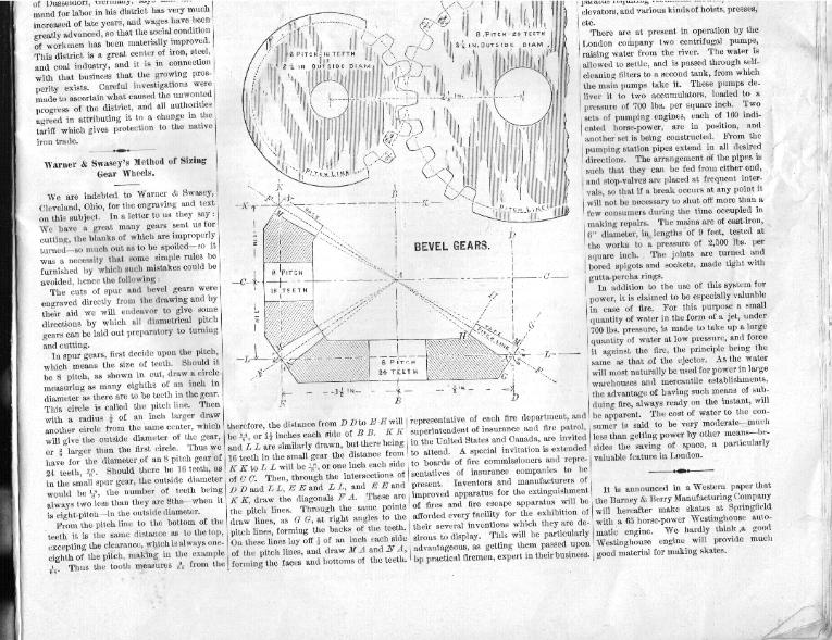
AMERICAN MACHINIST Layout and Drawing Bevel Gears the Traditional way. 30, 1884 6 (Illustration above) pg 7 top Auausv 30, 1884J AMERICAN MACHINIST 7 The Philadelphia. Electrical Exposition. pitch line to the bottom of the space; but the The lines H H are drawn parallel to G 0, clearance being provided for in the cutters, the the distance between them being the width Those having charge of the coming Elec- two gears would be laid out to mesh together of face. trical Exhibition at Philadelphia are doing I just $. - The face of the large gear should be themselves and the city credit by the vigor- These rules apply to all pitches, so that a turned to the lines M A, and the small gear: ous way they are pushing forward the work I five-pitch gear with 24 teeth would have an to N'A. For other pitches the same rules connected with the building. The outside of outside diameter of w- ; or if three-pitch, 40 apply. If four-pitch, use 4ths instead of the building is about completed, and the in- teeth, it would be Again,-if a;blank was 8ths; if three-pitch, ads, and so on. Bevel side work, prepa- ratory to taking in exhibits, i s pro - gressing rapidly. The foundations for 1 the,five engines that will run the ma- chinery are about finished, and the c b 7c shafting is being put up. Several of the engines will be i+' rz la of the Porter-Allen type, the larg-est 300-horse power. In the cen- ter of the hall there will be a fine elec- trical f o u n t a in, a+2j.1 FiU"v which is nearly completed. Among PROPORTIONING SLIDE VALPES.--(SEE PAGE 6). the curiosities that will be seen at the exhibition will be the 4 (-) in diameter and cut six pitch, it gears should always be turned to the diam- original Morse telegraph instrument, ;upon should contain 23 teeth. eters an-d angles of the drawings. which the first message ever telegraphed ' In laying out a pair of bevel gears, after •+• over a wire was sent from Washington to deciding upon the pitch, draw the center National Convention of Fire Engineers. Baltimore. As a comparison with the simple lines B B and C C, intersecting at right key instrument used by Professor Morse, angles at A. Then draw the lines D D and The twelfth annual convention of the Na- there will be exhibited a synchronous multi- E E the same distance each side of B B and I tional Association of Fire Engineers, accord- plex telegraphic machine, by which one ope- parallel to it, the distance from D D to E E ing to the official announcement signed by rator can send seventy-two messages at once being as many 8ths of an inch-if it be ?resident O'Connor and Secretary Hills, will over one wire. There will also be an electric eight-pitch—as there are teeth in the gear. be held in Chicago, commencing Tuesday, chicken-hatching machine and many other In the example the number of teeth is 24 ; September 9, 1884, at 12 M. The chief officer, interesting curiosities. In a recent consular repo Consul Warner, SRUR`GEARS. of Dusseldorf, Germany, says that the de- III IIIIII mand for labor in his district has very much ~I increased of late years, and wages have bee greatly advanced, so that the social condition ~I!!I~il of workmen has been materially improved. . P IT C H - 2 TEETH PITC This district is a great center of iron, steel, and coal industry, and it is in connection with that business that the growing pros- perity exists. Careful investigations made to ascertain what caused the unwonted progress of the district, and all authorities , agreed in attributing it to a change in the tariff which gives protection to the native iron trade. The. State of Hidalgo, Mexico, has voted to pay a subsidy of $1,500 per kilometer to the projectors of the new cable road soon to be constructed in the City of Pachuca by Mr. Andrew S. Halliday, who has the exclusive privilege throughout Mexico, during ten years, for building and operating all such roads. Mr. Halliday uses the same system now employed in San Francisco and Chicago. Mr. Jose Godoy, general agent of the Cable Road Company, left the capital on Wednesday for San Francisco, where he goes to obtain en- gineers, who will at once begin the • work of construct, ing the cable road at Pachuca. Arrangements are being made for similar roads in the Fig. 3 _ capital and other large cities of Mexico. Hydraulic Distribution of Power. According to Engineering, the hydraulic distribution of power in Hull has, so jar, proved entirely successful, and the company organized in 1882 to operate in London is meeting with the same kind of success. The plan is to force water by means of a hydraulic pumping engine into an accumulator, from which it is conveyed by divergent mains in various directions, under a pressure of about 700 lbs. per square inch. Power supplied in this way can be used for producing rotary motion, but its advantages are greater in apparatus requiring rectilineal motion, such as elevators, and various kinds of hoists, presses, etc. There are at present in operation by the London company two centrifugal pumps, raising water from the river. The water is allowed to settle, and is passed through self-cleaning filters to a second tank, from which the main pumps take it. These pumps deliver it to two accumulators, loaded to a pressure of 700 lbs. per square inch. Two sets of pumping engines, each of 160 indicated horse-power. are in position. and mand for labor in his district has very much increased of late years, and wages have been greatly advanced, so that the social condition of workmen has been materially improved. This district is a great center of iron, steel, and coal industry, and it is in connection with that business that the growing prosperity exists. Careful investigations were made to ascertain what caused the unwonted progress of the district, and all authorities agreed in attributing it to a change in the tariff which gives protection to the native iron trade. • Warner & Swasey's Method of Sizing Gear Wheels. We are indebted to Warner & Swasey, • Cleveland, Ohio, for the engraving and text on this subject. In a letter to us they say: We have a great many gears sent us for • cutting, the blanks of which are improperly • turned—so much out as to be spoiled-so it was a necessity that some simple rules be furnished by which such mistakes could be avoided, hence the following: The cuts of spur and bevel gears were engraved directly from the drawing and by • their aid we will endeavor to give some directions by which all diametrical pitch gears can be laid out preparatory to turning and cutting. In spur gears, first decide upon the pitch, which means the size of teeth. Should it be 8 pitch, as shown in cut, draw a circle • measuring as many eighths of an inch in diameter as there are to be teeth in the gear. This circle is called the pitch line. Then • with a radius $ of an inch larger draw another circle from the same center, which will give the outside diameter of the gear, or g larger than the first circle. Thus we • have for the diameter of an 8 pitch gear of 24 teeth, $e. Should there be 16 teeth, as in the small spur gear, the outside diameter would be g , the number of teeth being always two less than they are eths—when it is eight- pitch-in the outside diameter. From the pitch line to the bottom of the teeth it is the same distance as to the top, excepting the clearance, w>lich is always one-eighth of the pitch, making in the example $r• Thus the tooth measures from the therefore, the distance from D D to E E will representative of each fire department, and be g , or 12 inches each side of B B. K K superintendent of insurance and fire patrol, and L L are similarly drawn, but there being in the United States and Canada, are invited 16 teeth in the small gear the distance from to attend. A special invitation is extended K K to L L will be J, or, one inch each side to boards of fire commissioners and repre. of C C. Then, through the intersections of sentatives of insurance companies to be D D and L L, E E and L L, and E E and present. Inventors and manufacturers of K K, draw the diagonals F A. These are improved apparatus for the extinguishment the pitch lines. Through the same points of fires and fire escape apparatus will be draw lines, as C; G, at right angles to the afforded every facility for the exhibition of pitch lines, forming the backs of the teeth. their several inventions which they are de• On these lines lay off 8 of an inch each side sirous to display. This will be particularly of the pitch lines, and draw MA and N A, advantageous, as getting them passed upor forming the faces and bottoms of the teeth. bp practical firemen, expert in their business. parat,us requJ.IIu elevators, and various kinds of hoists, presses, etc. There are at present in operation by the London company two centrifugal pumps, raising water from the river. The water is allowed to settle, and is passed through self- cleaning filters to a second tank, from which the main pumps take it. These pumps de- liver I~Ii it to two accumulators, loaded to a pressure of 700 lbs. per square inch. Two sets of pumping engines, each of 160 indicated horse-power, are in position, and another set is being constructed. From the {!' pumping station pipes extend in all desired ! 1 directions. The arrangement of the pipes is such that they can be fed from either end, and stop-valves are placed at frequent inter- 0 vals, so that if a break occurs at any point it will not be necessary to shut off more than a few consumers during the time occupied in making repairs. The mains are of cast-iron, 8" diameter, ins lengths of 9 feet, tested at the works to a pressure of 2,500 lbs. per square inch.. The joints are turned and bored spigots and sockets, made tight with gutta-percha rings. In addition to the use of this system for power, it is claimed to be especially valuable in case of fire. For this purpose a small quantity of water in the form of a jet, under (I'i 700 lbs. pressure, is made to take up a large quantity of water at low pressure, and force it against the fire, the principle being the same as that of the ejector. As the water will most naturally be used for power in large warehouses and mercantile establishments, the advantage of having such means of sub- duing fire, always ready on the instant, will be apparent. The cost of water to the con- sumer { { is said to be very moderate-rnuch (; less than getting power by other means—besides the saving of space, a particularly valuable feature in London. It is announced in a Western paper that I` i the Barney & Berry Manufacturing Company will hereafter make skates at Springfield J I 1 with a 65 horse-power Westinghouse auto- matic 4111 engine. We hardly think a good Westinghouse engine will provide much good material for making skates. |
| American Machinist August 30 1884, vol. 7 no. 35 pg.6 6 |
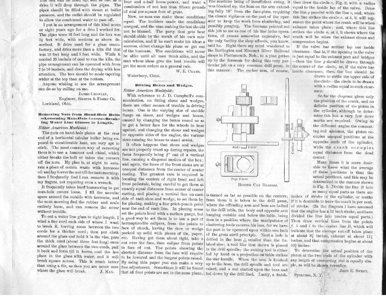
AMERICAN MACHINIST 30, 1884 6 when, after some years' running, they have Rubber Packing—Testing Boilers. distinguished themselves by their punctuality, Editor American Machinist: cleanliness, and especially by their sobriety. I notice an inquiry in your issue of August The position of the engine driver abroad is 16th about the use of rubber as packing for not well paid, it is true, but their lot is more an engine. While it might not be injurious enviable, especially, those where the State to iron, it would be injudicious to use it on manages. They are allowed so much a brass stems or rods, on account of the sulmonth for house rent; they have also mile phur which it contains, and which has ai money (meilengeld), besides coal and punc- corrosive an action on brass as acid has on tuality premiums. The working hours are iron. not so long, and on many lines every third Mr. William Lowe is sound on the boiler day is a day for rest. test question so far as the amount of work i done per square foot of heating surface goes, but it is hardly fair to lay all the blame on LETTERS FROM PRACTICAL MEN, the men who make the test, unless they have the control of setting the boilers, as the ratio Sand Drying Device, of heating to grate surface is arranged or Editor American Machinist: determined by the party building the boiler. In your issue of July 26 you ask anyone The conditions cannot be the same until having a satisfactory arrangement for drying boiler makers come to some uniform stand-sand to describe the same for the benefit of and of the proper amount of coal to be your readers. I have found the following an burned per square foot of grate per hour. excellent sand drying rig, and have had it in One builder believes in a slow combustion, use for a good many years: and puts in a large grate so as to get the full Take lengths of 4 inch gas pipe and make capacity of his boiler with a low fire. Anthem in sections of the length and width other builder, who has studied the habits of desired, using close pattern return bends on steam users, and is cognizant of the fact that the bottom coil, which will leave the pipes they usually run a boiler for all it will do inch apart. The sand will not drop through before purchasing new, or he may believe in that space when moist.` The second section a rapid combustion and consequent high should be made with open., pattern return temperature in the furnace, will put in a bends, which will leave the pipes 4 or 1 inch small grate, and the probabilities are that apart. The third and fourth sections should he will get the best results. be made with elbows and nipples-to leave I have two kinds of boilers set in the same the space 3 inches between the pipes. All room, and connected to the same chimney. The sections should be connected together so The makers of one style calculate fifteen that the steam will pass from the top section feet heating surface for one horse-power, and into the next below, and so on, with the one square foot of grate for two horse-power, outlet at the end of the bottom section. The and a combustion of about five or six pounds • sections should be 4 inches apart. " Build a of coal per square foot of grate. The make- • box around the pipes to hold the sand, and era of the other allow eleven feet heating leave a.. space under for the sand to drop. surface per horse-power, one foot grate for The box can be filled up, and as fast as it four and a-half horse-power, and want a dries it will drop through the pipes. The combustion of not less than fifteen pounds pipes should be filled with steam at boiler of coal per square foot of grate. pressure, and the outlet should be regulated Now, no man can make these conditions to allow the condensed water to pass off. equal. The builders made the conditions I put in an arrangement of this kind seven unequal, and the man making the test should or eight years ago for a firm I worked for, not be blamed. The party that gets beat The pipes were 16 feet long and the box was should abide by the •result of his own mis32 feet wide, with sections as above de- calculation, and if he can't make his ideas a scribed. It dries sand for a glass menu- success, either change his plans or get out factory, and dries more than a kiln did that of the business. The conditions will never, was 18 feet long and 3 feet wide. While it be alike until all men think alike, and the needed 25 bushels of coal to run the kiln, the man whose ideas give the best results will nine arrangement can be operated with from .'but if they don't vary more than g. of an ing reamer is put through the hole, and. the inch the distance can be divided between job passes along to the next man, and not a opposite points, and it will not seriously murmur is heard. The cut shows the parts affect their parallelism when in place. If so plainly as, to need no further description. the variation is more than this the cause . By the way, my Western friend called my must be looked for, and the points made attention to a kink which he had gotten up correct. About 12" of the face of the shoe on for boring car brasses on the drill, which he top and the same at bottom should be filed claims is the boss. The drawing will explain away, so that the box will pass by and avoid itself. The arrangement is very simple, and wearing a shoulder in the 'shoe, which will pays for itself in a short time. Brasses with cause a pound. ' A SHOPMAN. lugs and projections are accommodated by a different-shaped strap, and it is a matter of Method of Turning Ends of Rocker opinion as to whether a single cutter is used Arms-Boring Car "Boxes, or a standard-size milling cutter; but be Editor American Machinist: - says, "I prefer the mill, it being easily I was visiting a shop in the East, not long ground upon the emery wheel, and lasts a since, where several new engines were under long time." L. C. SHARP. course of construction, and, in noting the Plattsmouth, Neb. Proportioning Slide Valves and Determining the Elect of Difierent Proportions. Editor American Machinist: I wish to call the attention of such of your readers as have started to follow our method of — drawing valve-motion diagrams E to Fig. 1 (on opposite page) to show one other point, and that floe! cer Ar n _ is that the greatest distance from the line E to the circle A is the greatest width of port opening. Fig. 2 is simply a reproduction of Fig. 1, with the addition of a circle and line, which solves which are: to determine the point of exhaust opening, and the point at which compression begins. If the valve has inside lap—that is; if when the valve is set centrally the steam cannot escape from either end of the cylinder—then draw the circle c, Fig. 2, with a radius equal to the inside lap of the valve. Draw the line g parallel with the line e, and, where this line strikes the circle a, at h, it will represent the point where, the crank will be when exhaust takes place; and, where this line strikes the circle a, at 'i, it shows where the crank will be when the exhaust closes and compression begins. If the valve has neither lap nor inside clearance—that is, if the opening in the valve is just equal to the exhaust port and bridges —then the line g should be drawn through TURNING ROCKER ARMS. different points of interest, I was struck with the considerable amount of labor expended upon rocker arms, specially the turning up of the outer ends of the arms in the lathe. The machine being of insufficient swing, it was blocked up, the boss on the arm extend. ing fully 18" from the face-plate, requiring the closest vigilance on the part of the operstor to keep the work from chattering, and possibly gouging. The foreman pointed out this job to me as one of his fine lathe opera-;ions, of course somewhat expensive, •but he only facility the shop affords, you know, ;aid he. Right there my mind wandered to he Burlington and Missouri River Railroad shops in Plattsmouth, Neb., to a plan gotten ip by the foreman for doing, this very particular lob on a very common dri]l. nrraa- in. pressure, and the outlet should be regulated to allow the condensed water to pass off. I put in an arrangement of this kind seven or eight years ago for a firm I worked for. The pipes were 16 feet long and the box was 31 feet wide, with sections as above described. It dries sand for a glass manufactory, and dries more than a kiln did that was 18 feet long and 3 feet wide. While it needed 25 bushels of coal to run the kiln, the pipe arrangement can be operated with from 7 to 10 bushels, and does the drying with less attention. The box should be made tapering wider at the top than at the bottom. Anyone wishing to see the arrangement can do so by calling on me. JAMES CROWLEY, ' Engineer, Stearns & Foster Co. Lockland, Ohio. Removing Nuts from Hand-Hole Bolts —Loosening 1!Lan-IWole Covers—Break- ing Water Line Glasses to Length. Editor American Machinist: The nuts on hand-hole plates at the rear end of a horizontal tubular boiler being exposed to considerable heat, are very apt to stick. The most common way of removing them is to use a hammer and chisel, which either breaks the bolt or takes the corners off the nuts. My plan is, at night to saturate a piece of cotton waste with kerosene oil and lay it over the nut till the next morning; then I fregluently find I can remove it with my fingers, not requiring even a wrench. It frequently takes hard hammering to get man-hole covers loose. I fill the annular space around the outside with kerosene, and the next morning find the rubber and scale entirely loose, and can remove the cover without trouble. To cut a water line glass to right length, I wind a fine cord each side of where I want to break it, leaving room between the two cords for a thicker cord; then put cloth around the glass and hold it in the vise, pass the thick cord (about three feet long) once around the glass between the two cords, pull it back and forth till it burns, cool the hot place in the glass with water, and it will break square across. This is much better than using a file, as then you are never sure where the glass will break, J. i 1Ay.v. cue' per square loot or grate. Now, no man can make these conditions equal. The builders made the conditions unequal, and the man making the test should not be blamed. The party that gets beat should abide by the result of his own miscalculation, and if he can't make his ideas a success, either change his plans or get out of the business. The conditions will never be alike until all men think alike, and the man whose ideas give the best results will get the most orders as a general rule. W. E. CRANE. Waterbury, Conn. Driving Boxes and Wedges. Editor American Machinist: With reference to J. D. Campbell's communication, on fitting shoes and wedges, there are other causes of trouble in driving' boxes. One is the varying size of outside flange on shoes, and wedges and boxes, caused by changing the boxes round so as to get a better face for the wheels to bear against, and changing the shoes and wedges to opposite sides of the engine, the various sizes causing the boxes to stand atwist. It often happens that shoes and wedges are not properly trued up during repairs, the faces frequently being g" out of a vertical line, causing a diagonal motion of the box; and again, the faces of the front shoes are at unequal distances from the center of center casting. The greatest care is required in locating the centers of right front and left front pedestals, being careful to get them at exactly equal distances from center of center casting, and placing a vertical line on each side of each shoe and wedge, to set them by for planing, making a fine prick- punch point near the end of each line. In planing some set the points level with a surface gauge, but a good way to set them is to use a pair of hermaphrodite calipers, from the points to face of chuck, having the shoe or wedge packed up solid with pieces of tin, paper, etc. Having got them about right, take a cut over the face, then caliper from points to face of cut. The points showing the shortest distance from the face will require to be lowered and the longest points raised. By using thin paper you can make a very fine adjustment. Sometimes it will be found that all four points are not in the same plane,rug runny .ro iivui Lau lave-yiwlc, lWKuuiug, the closest vigilance on the part of the operator to keep the work from chattering, and possibly gouging. The foreman pointed out this job to me as one of his fine lathe operations, of course somewhat expensive, but the only facility the shop affords, you know, said he. Right there my mind wandered to the Burlington and Missouri River Railroad shops in Plattsmouth, Neb., to a plan gotten' up by the foreman for doing this very particular job on a very common drill press, in this manner: The rocker arm, of course, Top View BORING CAR BRASSES. is turned as far as possible on the centers; from them it is taken to the drill press, where the offending arm and boss are bolted to the drill table, the body and opposite arm hanging outside and below the table, being then in a position where the manipulator of chattering tools mourns his loss, for we have the part to be operated upon within one inch of the great anvil principle. Next a hole is drilled in the boss Q smaller than the finished size; a tool like that shown is placed in the drill spindle; the cutting tool is either fed by hand or a projection on table strikes the star handle. When the arm is finished up to the boss, the drill spindle and tool are raised, and a cut started upon the boss and fed down by the drill feed, Lastly, a finish. rite nue(y paliulel wal.ln Unu uutl c, $uu, wuere this line strikes the circle a, at h, it will represent the point where the crank will be when exhaust takes place; and, where this line strikes the circle a,_ at i, it shows where the crank will be when the exhaust closes and compression begins. If the valve has neither lap nor inside clearance that is, if the opening in the valve is just equal to the exhaust port and bridges —then the line g should be drawn through the center of the circle, or, if the valve has inside clearance, then the line should be drawn to strike the upper side of the circle-the circle to be drawn with a radius equal to such clear- ance. So far the diagram gives only the position of the crank, and no definite position of the piston in the cylinder, although to determine this but a very few more marks are required. Owing to v — the different angles the connect- " ing rod assumes, the piston occupies unequal positions at the opposite "'ends of the cylinder, while the crank occupies equal distances from the dead center. Many times it is more desir- able to know what the average of these positions is than the actual positions, and this may be determined in the manner shown in Fig. 3. Divide the line B into as many equal parts as there are inches of stroke in the cylinder, or tenths if it is desirable to have the result in per cent. of stroke. (In the diagram I have assumed that the engine has a 12 inch stroke, and have divided the line into twelve equal parts.) Then draw vertical lines from the points f, It and i-to the center line B, which will indicate that the average cut-off takes place at about 84 inches, exhaust at about 11; inches, and that compression begins at about 104 inches. To determine the actual position of the piston at the two 'epds of the cylinder with any length of connecting rod is equally simple, as will be shown hereafter. Jo$N E. SWEET. Syracuse, N. Y. |
AMERICAN MACHINIST 30, 1884 6 when, after some years' running, they have Rubber Packing—Testing Boilers. distinguished themselves by their punctuality, Editor American Machinist: cleanliness, and especially by their sobriety. I notice an inquiry in your issue of August The position of the engine driver abroad is 16th about the use of rubber as packing for not well paid, it is true, but their lot is more an engine. While it might not be injurious enviable, especially, those where the State to iron, it would be injudicious to use it on manages. They are allowed so much a brass stems or rods, on account of the sulmonth for house rent; they have also mile phur which it contains, and which has ai money (meilengeld), besides coal and punc- corrosive an action on brass as acid has on tuality premiums. The working hours are iron. not so long, and on many lines every third Mr. William Lowe is sound on the boiler day is a day for rest. test question so far as the amount of work i done per square foot of heating surface goes, but it is hardly fair to lay all the blame on LETTERS FROM PRACTICAL MEN, the men who make the test, unless they have the control of setting the boilers, as the ratio Sand Drying Device, of heating to grate surface is arranged or Editor American Machinist: determined by the party building the boiler. In your issue of July 26 you ask anyone The conditions cannot be the same until having a satisfactory arrangement for drying boiler makers come to some uniform stand-sand to describe the same for the benefit of and of the proper amount of coal to be your readers. I have found the following an burned per square foot of grate per hour. excellent sand drying rig, and have had it in One builder believes in a slow combustion, use for a good many years: and puts in a large grate so as to get the full Take lengths of 4 inch gas pipe and make capacity of his boiler with a low fire. Anthem in sections of the length and width other builder, who has studied the habits of desired, using close pattern return bends on steam users, and is cognizant of the fact that the bottom coil, which will leave the pipes they usually run a boiler for all it will do inch apart. The sand will not drop through before purchasing new, or he may believe in that space when moist.` The second section a rapid combustion and consequent high should be made with open., pattern return temperature in the furnace, will put in a bends, which will leave the pipes 4 or 1 inch small grate, and the probabilities are that apart. The third and fourth sections should he will get the best results. be made with elbows and nipples-to leave I have two kinds of boilers set in the same the space 3 inches between the pipes. All room, and connected to the same chimney. The sections should be connected together so The makers of one style calculate fifteen that the steam will pass from the top section feet heating surface for one horse-power, and into the next below, and so on, with the one square foot of grate for two horse-power, outlet at the end of the bottom section. The and a combustion of about five or six pounds • sections should be 4 inches apart. " Build a of coal per square foot of grate. The make- • box around the pipes to hold the sand, and era of the other allow eleven feet heating leave a.. space under for the sand to drop. surface per horse-power, one foot grate for The box can be filled up, and as fast as it four and a-half horse-power, and want a dries it will drop through the pipes. The combustion of not less than fifteen pounds pipes should be filled with steam at boiler of coal per square foot of grate. pressure, and the outlet should be regulated Now, no man can make these conditions to allow the condensed water to pass off. equal. The builders made the conditions I put in an arrangement of this kind seven unequal, and the man making the test should or eight years ago for a firm I worked for, not be blamed. The party that gets beat The pipes were 16 feet long and the box was should abide by the •result of his own mis32 feet wide, with sections as above de- calculation, and if he can't make his ideas a scribed. It dries sand for a glass menu- success, either change his plans or get out factory, and dries more than a kiln did that of the business. The conditions will never, was 18 feet long and 3 feet wide. While it be alike until all men think alike, and the needed 25 bushels of coal to run the kiln, the man whose ideas give the best results will nine arrangement can be operated with from .'but if they don't vary more than g. of an ing reamer is put through the hole, and. the inch the distance can be divided between job passes along to the next man, and not a opposite points, and it will not seriously murmur is heard. The cut shows the parts affect their parallelism when in place. If so plainly as, to need no further description. the variation is more than this the cause . By the way, my Western friend called my must be looked for, and the points made attention to a kink which he had gotten up correct. About 12" of the face of the shoe on for boring car brasses on the drill, which he top and the same at bottom should be filed claims is the boss. The drawing will explain away, so that the box will pass by and avoid itself. The arrangement is very simple, and wearing a shoulder in the 'shoe, which will pays for itself in a short time. Brasses with cause a pound. ' A SHOPMAN. lugs and projections are accommodated by a different-shaped strap, and it is a matter of Method of Turning Ends of Rocker opinion as to whether a single cutter is used Arms-Boring Car "Boxes, or a standard-size milling cutter; but be Editor American Machinist: - says, "I prefer the mill, it being easily I was visiting a shop in the East, not long ground upon the emery wheel, and lasts a since, where several new engines were under long time." L. C. SHARP. course of construction, and, in noting the Plattsmouth, Neb. Proportioning Slide Valves and Determining the Elect of Difierent Proportions. Editor American Machinist: I wish to call the attention of such of your readers as have started to follow our method of — drawing valve-motion diagrams E to Fig. 1 (on opposite page) to show one other point, and that floe! cer Ar n _ is that the greatest distance from the line E to the circle A is the greatest width of port opening. Fig. 2 is simply a reproduction of Fig. 1, with the addition of a circle and line, which solves which are: to determine the point of exhaust opening, and the point at which compression begins. If the valve has inside lap—that is; if when the valve is set centrally the steam cannot escape from either end of the cylinder—then draw the circle c, Fig. 2, with a radius equal to the inside lap of the valve. Draw the line g parallel with the line e, and, where this line strikes the circle a, at h, it will represent the point where, the crank will be when exhaust takes place; and, where this line strikes the circle a, at 'i, it shows where the crank will be when the exhaust closes and compression begins. If the valve has neither lap nor inside clearance—that is, if the opening in the valve is just equal to the exhaust port and bridges —then the line g should be drawn through TURNING ROCKER ARMS. different points of interest, I was struck with the considerable amount of labor expended upon rocker arms, specially the turning up of the outer ends of the arms in the lathe. The machine being of insufficient swing, it was blocked up, the boss on the arm extend. ing fully 18" from the face-plate, requiring the closest vigilance on the part of the operstor to keep the work from chattering, and possibly gouging. The foreman pointed out this job to me as one of his fine lathe opera-;ions, of course somewhat expensive, •but he only facility the shop affords, you know, ;aid he. Right there my mind wandered to he Burlington and Missouri River Railroad shops in Plattsmouth, Neb., to a plan gotten ip by the foreman for doing, this very particular lob on a very common dri]l. nrraa- in. pressure, and the outlet should be regulated to allow the condensed water to pass off. I put in an arrangement of this kind seven or eight years ago for a firm I worked for. The pipes were 16 feet long and the box was 31 feet wide, with sections as above described. It dries sand for a glass manufactory, and dries more than a kiln did that was 18 feet long and 3 feet wide. While it needed 25 bushels of coal to run the kiln, the pipe arrangement can be operated with from 7 to 10 bushels, and does the drying with less attention. The box should be made tapering wider at the top than at the bottom. Anyone wishing to see the arrangement can do so by calling on me. JAMES CROWLEY, ' Engineer, Stearns & Foster Co. Lockland, Ohio. Removing Nuts from Hand-Hole Bolts —Loosening 1!Lan-IWole Covers—Break- ing Water Line Glasses to Length. Editor American Machinist: The nuts on hand-hole plates at the rear end of a horizontal tubular boiler being exposed to considerable heat, are very apt to stick. The most common way of removing them is to use a hammer and chisel, which either breaks the bolt or takes the corners off the nuts. My plan is, at night to saturate a piece of cotton waste with kerosene oil and lay it over the nut till the next morning; then I fregluently find I can remove it with my fingers, not requiring even a wrench. It frequently takes hard hammering to get man-hole covers loose. I fill the annular space around the outside with kerosene, and the next morning find the rubber and scale entirely loose, and can remove the cover without trouble. To cut a water line glass to right length, I wind a fine cord each side of where I want to break it, leaving room between the two cords for a thicker cord; then put cloth around the glass and hold it in the vise, pass the thick cord (about three feet long) once around the glass between the two cords, pull it back and forth till it burns, cool the hot place in the glass with water, and it will break square across. This is much better than using a file, as then you are never sure where the glass will break, J. i 1Ay.v. cue' per square loot or grate. Now, no man can make these conditions equal. The builders made the conditions unequal, and the man making the test should not be blamed. The party that gets beat should abide by the result of his own miscalculation, and if he can't make his ideas a success, either change his plans or get out of the business. The conditions will never be alike until all men think alike, and the man whose ideas give the best results will get the most orders as a general rule. W. E. CRANE. Waterbury, Conn. Driving Boxes and Wedges. Editor American Machinist: With reference to J. D. Campbell's communication, on fitting shoes and wedges, there are other causes of trouble in driving' boxes. One is the varying size of outside flange on shoes, and wedges and boxes, caused by changing the boxes round so as to get a better face for the wheels to bear against, and changing the shoes and wedges to opposite sides of the engine, the various sizes causing the boxes to stand atwist. It often happens that shoes and wedges are not properly trued up during repairs, the faces frequently being g" out of a vertical line, causing a diagonal motion of the box; and again, the faces of the front shoes are at unequal distances from the center of center casting. The greatest care is required in locating the centers of right front and left front pedestals, being careful to get them at exactly equal distances from center of center casting, and placing a vertical line on each side of each shoe and wedge, to set them by for planing, making a fine prick- punch point near the end of each line. In planing some set the points level with a surface gauge, but a good way to set them is to use a pair of hermaphrodite calipers, from the points to face of chuck, having the shoe or wedge packed up solid with pieces of tin, paper, etc. Having got them about right, take a cut over the face, then caliper from points to face of cut. The points showing the shortest distance from the face will require to be lowered and the longest points raised. By using thin paper you can make a very fine adjustment. Sometimes it will be found that all four points are not in the same plane,rug runny .ro iivui Lau lave-yiwlc, lWKuuiug, the closest vigilance on the part of the operator to keep the work from chattering, and possibly gouging. The foreman pointed out this job to me as one of his fine lathe operations, of course somewhat expensive, but the only facility the shop affords, you know, said he. Right there my mind wandered to the Burlington and Missouri River Railroad shops in Plattsmouth, Neb., to a plan gotten' up by the foreman for doing this very particular job on a very common drill press, in this manner: The rocker arm, of course, Top View BORING CAR BRASSES. is turned as far as possible on the centers; from them it is taken to the drill press, where the offending arm and boss are bolted to the drill table, the body and opposite arm hanging outside and below the table, being then in a position where the manipulator of chattering tools mourns his loss, for we have the part to be operated upon within one inch of the great anvil principle. Next a hole is drilled in the boss Q smaller than the finished size; a tool like that shown is placed in the drill spindle; the cutting tool is either fed by hand or a projection on table strikes the star handle. When the arm is finished up to the boss, the drill spindle and tool are raised, and a cut started upon the boss and fed down by the drill feed, Lastly, a finish. rite nue(y paliulel wal.ln Unu uutl c, $uu, wuere this line strikes the circle a, at h, it will represent the point where the crank will be when exhaust takes place; and, where this line strikes the circle a,_ at i, it shows where the crank will be when the exhaust closes and compression begins. If the valve has neither lap nor inside clearance that is, if the opening in the valve is just equal to the exhaust port and bridges —then the line g should be drawn through the center of the circle, or, if the valve has inside clearance, then the line should be drawn to strike the upper side of the circle-the circle to be drawn with a radius equal to such clear- ance. So far the diagram gives only the position of the crank, and no definite position of the piston in the cylinder, although to determine this but a very few more marks are required. Owing to v — the different angles the connect- " ing rod assumes, the piston occupies unequal positions at the opposite "'ends of the cylinder, while the crank occupies equal distances from the dead center. Many times it is more desir- able to know what the average of these positions is than the actual positions, and this may be determined in the manner shown in Fig. 3. Divide the line B into as many equal parts as there are inches of stroke in the cylinder, or tenths if it is desirable to have the result in per cent. of stroke. (In the diagram I have assumed that the engine has a 12 inch stroke, and have divided the line into twelve equal parts.) Then draw vertical lines from the points f, It and i-to the center line B, which will indicate that the average cut-off takes place at about 84 inches, exhaust at about 11; inches, and that compression begins at about 104 inches. To determine the actual position of the piston at the two 'epds of the cylinder with any length of connecting rod is equally simple, as will be shown hereafter. Jo$N E. SWEET. Syracuse, N. Y. |
| American Machinist August 30 1884, vol. 7 no. 35 pg. 7 6 |

| American Machinist August 30 1884, vol. 7 no. 35 pg.7 6 |
| American Machinist August 30 1884, vol. 7 no. 35 pg.6 6 |
American Machinist August 30 1884, vol. 7 no. 35 pg. 5